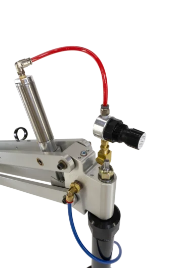
Encoder Options
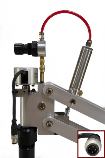
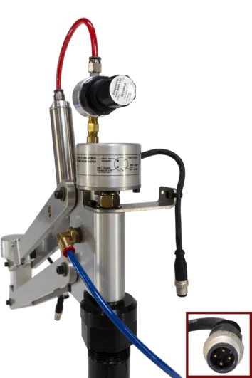
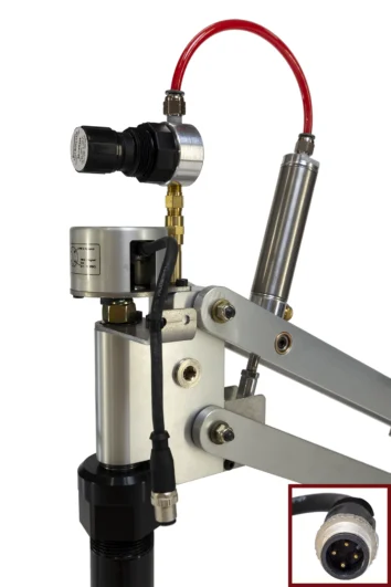
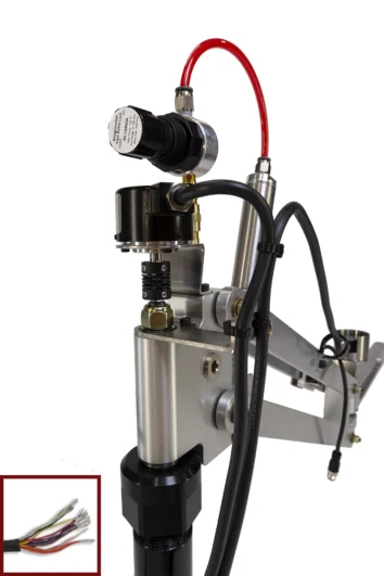
ENCODER IDENTIFICATION | IOSA | AVSA | AMSA | GCSA | XXSA |
|---|---|---|---|---|---|
SMART ARM MODEL CONFIGURATION EXAMPLE | EL815-UV-IOSA | EL815-UV-AVSA | EL815-UV-AMSA | EL815-UV-GCSA | EL815-UV-XXSA |
OUTPUT | IO-Link Spec V1.1 to IEC 61131-9, Smart Sensor Profile. Programmable Parameters for Zero point offset, averaging and rotational direction. | Analog 0.1 to 10.0 VDC | Analog 4 to 20 mA | Parallel Gray Code NPN open Collector Negative Logic (active low) | N/A |
ENCODER CONNECTIONS PER X/Y SMART-ARM | [2] short cables (150 mm long) with M12, 4 Pin Male Connectors | [2] short cables (150 mm long) with M12, 4 Pin Male Connectors | [2] short cables (150 mm long) with M12, 4 Pin Male Connectors | [2] cables 55" (140 cm) long with flying leads having 13 conductors each + shield | N/A |
MECHANICAL DESCRIPTION | Hall Effect - Encoder. No moving sensor parts. Mechanically Decoupled from Tool Arm Shafts (No shaft coupler). Unlimited life. | Hall Effect - Encoder. No moving sensor parts. Mechanically Decoupled from Tool Arm Shafts (No shaft coupler). Unlimited life. | Hall Effect - Encoder. No moving sensor parts. Mechanically Decoupled from Tool Arm Shafts (No shaft coupler). Unlimited life. | Mechanical rotary encoders coupled to smart-arm shafts by an alignment coupler. Long Life | Encoder Ready Arm with 8mm Ø x .375" L shaft extensions and 10-32 tapped holes for your bracket and encoders. |
PLC I/O REQUIREMENT | 1 input per encoder | 1 input per encoder | 1 input per encoder | 11 inputs per encoder | N/A |
ABSOLUTE RESOLUTION | 14 bit (16,384) | 12 bit (4096) | 12 bit (4096) | 11 bit (2048) | N/A |
REPEATABILITY (Each Encoder) | 0.10⁰ | 0.10⁰ | 0.10⁰ | 0.09⁰ | N/A |
MEASURING RANGE | 360⁰ | 360⁰ | 360⁰ | 360⁰ | N/A |
INPUT SUPPLY VOLTAGE (24 VDC Nominal) | 18 - 30 VDC | 18 - 30 VDC | 18 - 30 VDC | 11 - 26 VDC | N/A |
INPUT SUPPLY CURRENT | Follow IO-Link Standards | 15mA per Encoder, 30 mA total | 15mA per Encoder, 30 mA total | 70mA per Encoder 140 mA total | N/A |
CONTROLLER LOAD | N/A - Use a certified IO-Link Master | 10kΩ or greater | burden 500 Ω Max | Sinking current 32mA max | Residual voltage 0.4 V max @ ≤16mA | 1.5V max @ >16mA to 32mA | N/A |
PIN OUT | Pin 1, 24 V DC in | Pin 1, 24 V DC in | Pin 1, 24 V DC in | Blue wire - 0V | N/A |
Pin 2, not connected | Pin 2, 0.1 - 10 V out | Pin 2, 4 - 20 mA out | Brown wire - 24V |
| |
Pin 3, GROUND | Pin 3, GROUND | Pin 3, GROUND | Black wire - bit 0 |
| |
Pin 4, C/Q | Pin 4, not connected | Pin 4, not connected | Red wire - bit 1 |
| |
|
|
| Orange wire - bit 2 |
| |
|
|
| Yellow wire - bit 3 |
| |
|
|
| Green wire - bit 4 |
| |
|
|
| Purple wire - bit 5 |
| |
|
|
| Gray wire - bit 6 |
| |
|
|
| White wire - bit 7 |
| |
|
|
| Black / White wire - bit 8 |
| |
|
|
| Red / White wire - bit 9 |
| |
|
|
| Orange / White wire - bit 10 |
| |
|
|
| Shield - GROUND |
| |
ENCODER DATA FILES |
|
IOSA
IO-Link Digital Models
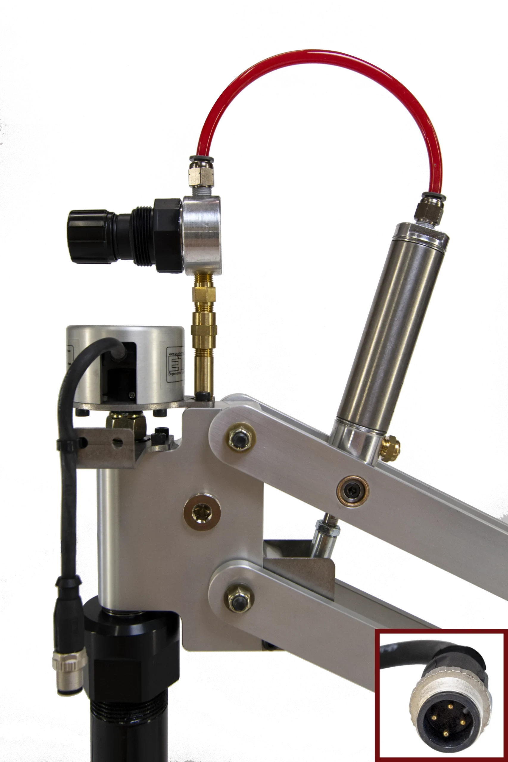
ENCODER IDENTIFICATION | IOSA |
|---|---|
SMART ARM MODEL CONFIGURATION EXAMPLE | EL815-UV-IOSA |
OUTPUT | IO-Link Spec V1.1 to IEC 61131-9, Smart Sensor Profile. Programmable Parameters for Zero point offset, averaging and rotational direction. |
ENCODER CONNECTIONS PER X/Y SMART-ARM | [2] short cables (150 mm long) with M12, 4 Pin Male Connectors |
MECHANICAL DESCRIPTION | Hall Effect - Encoder. No moving sensor parts. Mechanically Decoupled from Tool Arm Shafts (No shaft coupler). Unlimited life. |
PLC I/O REQUIREMENT | 1 input per encoder |
ABSOLUTE RESOLUTION | 14 bit (16,384) |
REPEATABILITY (Each Encoder) | 0.10⁰ |
MEASURING RANGE | 360⁰ |
INPUT SUPPLY VOLTAGE (24 VDC Nominal) | 18 - 30 VDC |
INPUT SUPPLY CURRENT | Follow IO-Link Standards |
CONTROLLER LOAD | N/A - Use a certified IO-Link Master |
PIN OUT | Pin 1, 24 V DC in |
Pin 2, not connected | |
Pin 3, GROUND | |
Pin 4, C/Q | |
ENCODER DATA FILES |
AVSA
Analog Voltage Models
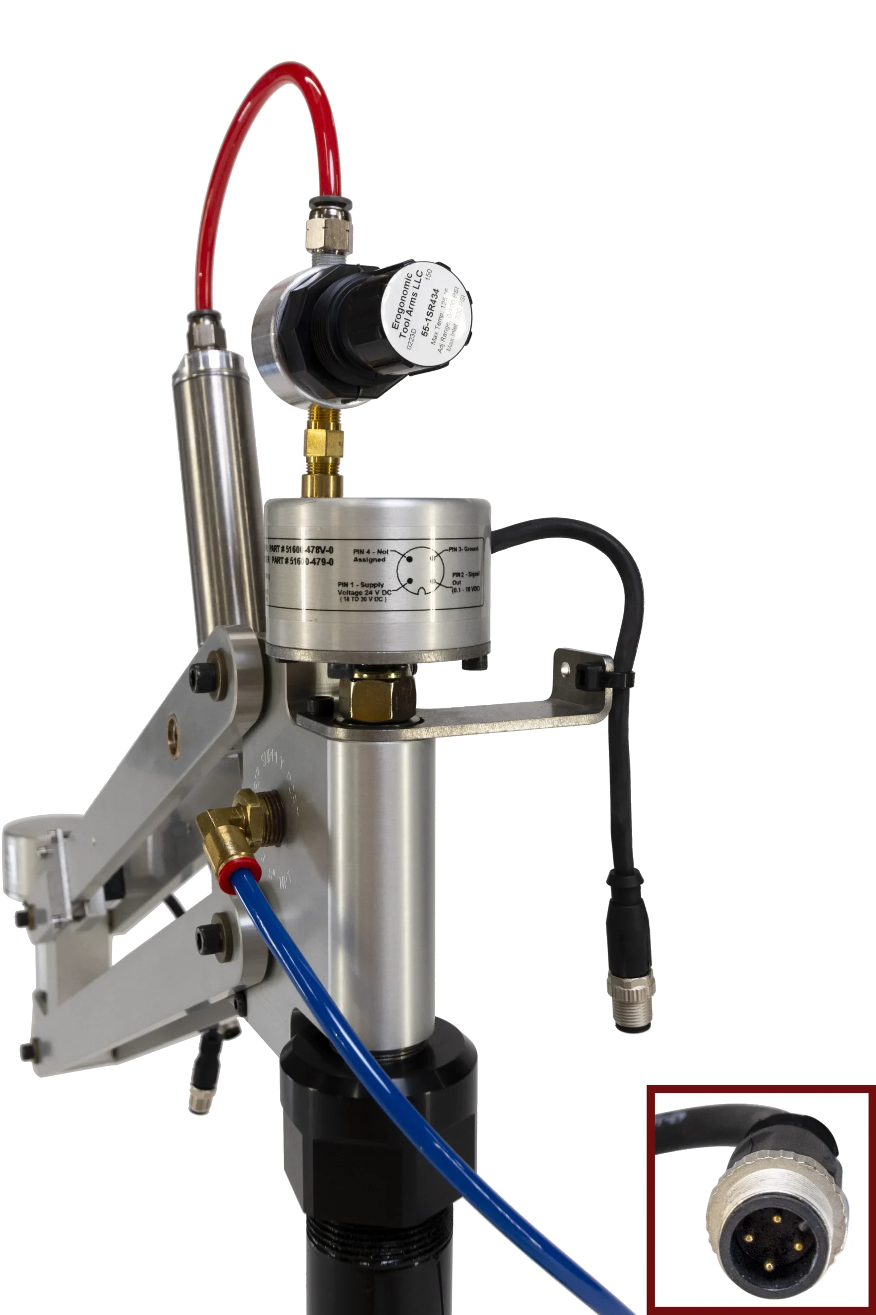
ENCODER IDENTIFICATION | AVSA |
|---|---|
SMART ARM MODEL CONFIGURATION EXAMPLE | EL815-UV-AVSA |
OUTPUT | Analog 0.1 to 10.0 VDC |
ENCODER CONNECTIONS PER X/Y SMART-ARM | [2] short cables (150 mm long) with M12, 4 Pin Male Connectors |
MECHANICAL DESCRIPTION | Hall Effect - Encoder. No moving sensor parts. Mechanically Decoupled from Tool Arm Shafts (No shaft coupler). Unlimited life. |
PLC I/O REQUIREMENT | 1 input per encoder |
ABSOLUTE RESOLUTION | 12 bit (4096) |
REPEATABILITY (Each Encoder) | 0.10⁰ |
MEASURING RANGE | 360⁰ |
INPUT SUPPLY VOLTAGE (24 VDC Nominal) | 18 - 30 VDC |
INPUT SUPPLY CURRENT | 15mA per Encoder, 30 mA total |
CONTROLLER LOAD | 10kΩ or greater |
PIN OUT | Pin 1, 24 V DC in |
Pin 2, 0.1 - 10 V out | |
Pin 3, GROUND | |
Pin 4, not connected | |
ENCODER DATA FILES |
AMSA
Analog Current Models
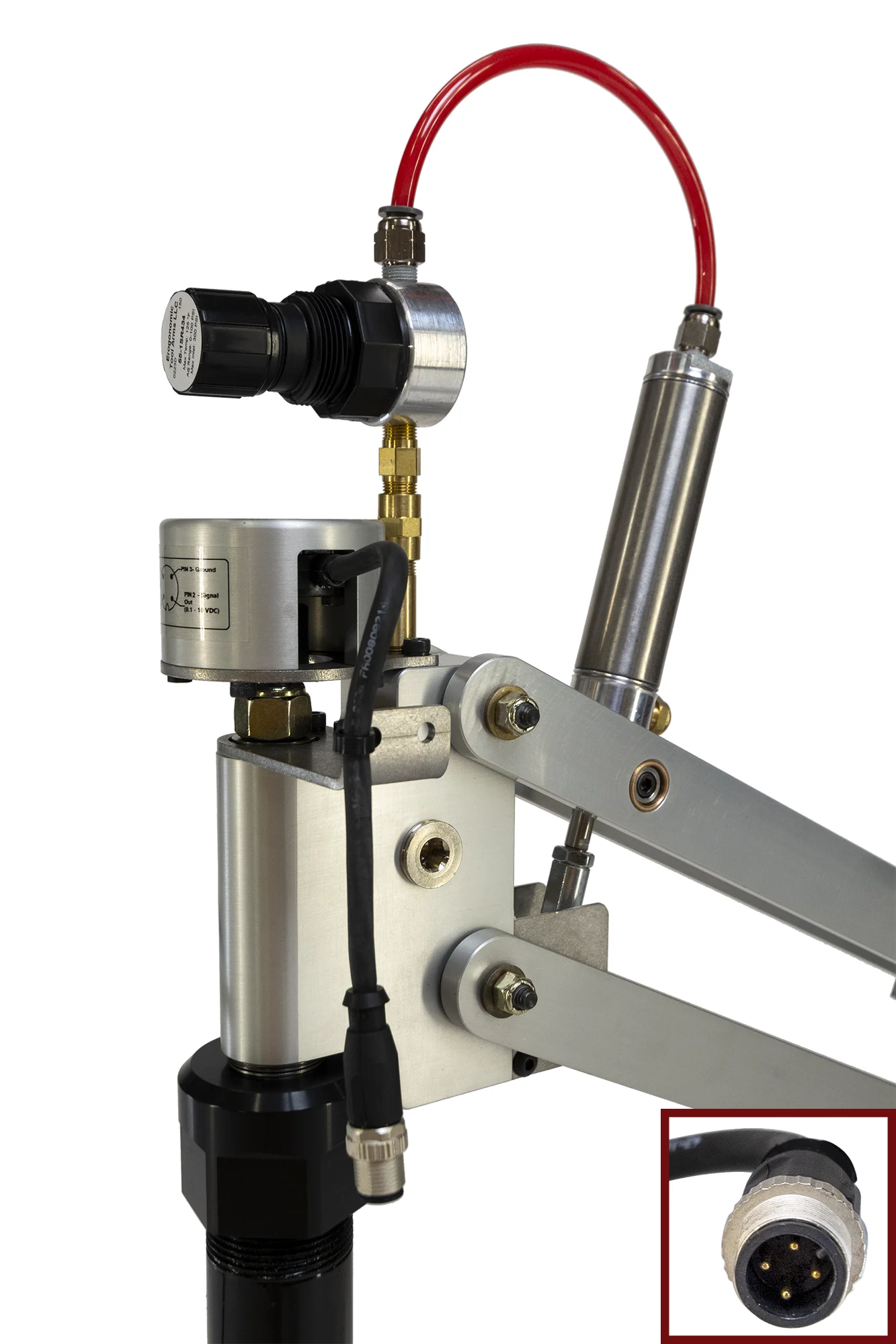
ENCODER IDENTIFICATION | AMSA |
|---|---|
SMART ARM MODEL CONFIGURATION EXAMPLE | EL815-UV-AMSA |
OUTPUT | Analog 4 to 20 mA |
ENCODER CONNECTIONS PER X/Y SMART-ARM | [2] short cables (150 mm long) with M12, 4 Pin Male Connectors |
MECHANICAL DESCRIPTION | Hall Effect - Encoder. No moving sensor parts. Mechanically Decoupled from Tool Arm Shafts (No shaft coupler). Unlimited life. |
PLC I/O REQUIREMENT | 1 input per encoder |
ABSOLUTE RESOLUTION | 12 bit (4096) |
REPEATABILITY (Each Encoder) | 0.10⁰ |
MEASURING RANGE | 360⁰ |
INPUT SUPPLY VOLTAGE (24 VDC Nominal) | 18 - 30 VDC |
INPUT SUPPLY CURRENT | 15mA per Encoder, 30 mA total |
CONTROLLER LOAD | burden 500 Ω Max |
PIN OUT | Pin 1, 24 V DC in |
Pin 2, 4 - 20 mA out | |
Pin 3, GROUND | |
Pin 4, not connected | |
ENCODER DATA FILES |
GCSA
Graycode Models
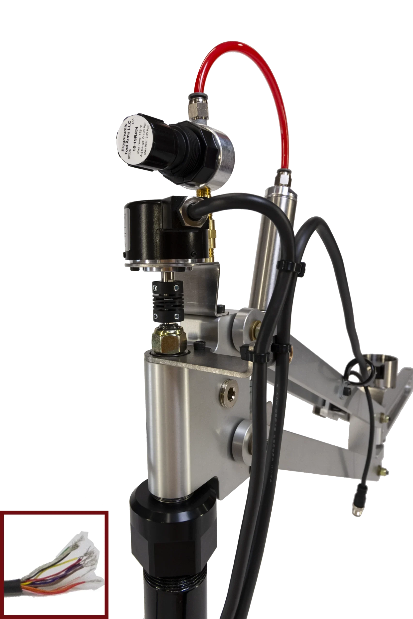
ENCODER IDENTIFICATION | GCSA |
|---|---|
SMART ARM MODEL CONFIGURATION EXAMPLE | EL815-UV-GCSA |
OUTPUT | Parallel Gray Code NPN open Collector Negative Logic (active low) |
ENCODER CONNECTIONS PER X/Y SMART-ARM | [2] cables 55" (140 cm) long with flying leads having 13 conductors each + shield |
MECHANICAL DESCRIPTION | Mechanical rotary encoders coupled to smart-arm shafts by an alignment coupler. Long Life |
PLC I/O REQUIREMENT | 11 inputs per encoder |
ABSOLUTE RESOLUTION | 11 bit (2048) |
REPEATABILITY (Each Encoder) | 0.09⁰ |
MEASURING RANGE | 360⁰ |
INPUT SUPPLY VOLTAGE (24 VDC Nominal) | 11 - 26 VDC |
INPUT SUPPLY CURRENT | 70mA per Encoder 140 mA total |
CONTROLLER LOAD | Sinking current 32mA max | Residual voltage 0.4 V max @ ≤16mA | 1.5V max @ >16mA to 32mA |
PIN OUT | Blue wire - 0V |
Brown wire - 24V | |
Black wire - bit 0 | |
Red wire - bit 1 | |
Orange wire - bit 2 | |
Yellow wire - bit 3 | |
Green wire - bit 4 | |
Purple wire - bit 5 | |
Gray wire - bit 6 | |
White wire - bit 7 | |
Black / White wire - bit 8 | |
Red / White wire - bit 9 | |
Orange / White wire - bit 10 | |
Shield - GROUND | |
ENCODER DATA FILES |
XXSA
Encoder Ready Models
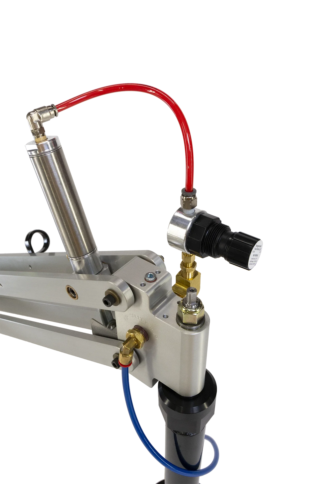
ENCODER IDENTIFICATION | XXSA |
|---|---|
SMART ARM MODEL CONFIGURATION EXAMPLE | EL815-UV-XXSA |
OUTPUT | N/A |
ENCODER CONNECTIONS PER X/Y SMART-ARM | N/A |
MECHANICAL DESCRIPTION | Encoder Ready Arm with 8mm Ø x .375" L shaft extensions and 10-32 tapped holes for your bracket and encoders. |
PLC I/O REQUIREMENT | N/A |
ABSOLUTE RESOLUTION | N/A |
REPEATABILITY (Each Encoder) | N/A |
MEASURING RANGE | N/A |
INPUT SUPPLY VOLTAGE (24 VDC Nominal) | N/A |
INPUT SUPPLY CURRENT | N/A |
CONTROLLER LOAD | N/A |
PIN OUT | N/A |
About Encoder Accuracy
There are many factors that affect fastener location accuracy. Some of the common factors are bit or socket extension wiggle, tool spindle compliance and spring loaded spindle collapse, component dimensional consistency, accuracy of the component location in the fixture, and of course, repeatability and accuracy of the smart-arm encoders. These factors are not usually critical unless the fastener locations are very close together (almost touching).
When all of the physical location issues are optimized, then typically your controls should be able to read our encoder outputs to differentiate between fasteners within approximately 1/8” (3mm).
Get in touch with us today

Ergonomic Tool Arms, LLC
P.O. Box 534
Doylestown, PA 18901
Phone: 855 TOOL ARM
Phone: (855) 866-5276
contact@toolarms.com

All rights reserved to SmartArms.com

